

RayCoupler
Hardware
Compact HF/VHF directional coupler in two population configurations—200 W and 2 kW— with forward/reflected outputs for SWR, Return Loss, and power measurement. Pairs with RaySspaController and RayRigAntSw, and is intentionally designed for easy integration into third-party amplifiers, meters, or station controllers.
Overview
RayCoupler is a tandem-match HF/VHF directional coupler that provides forward and reflected detector outputs for instrumentation or controller inputs. The design provides two populations on the same board: a 200 W variant for bench/driver chains and a 2 kW high-power variant for linear amplifiers.
Public Engineering Reference — AS-IS. RayCouplers is now available as open hardware under CERN-OHL-P v2.0 for study, independent construction, testing, modification and improvement. The repository includes editable KiCad sources, population BOMs, manufacturing files, construction documentation and historical calibration material. No commercial certification or guaranteed performance is claimed.
One 70 × 102 mm common PCB supports both configurations through component and transformer populations. Historically fabricated hardware was assembled and RF-tested; the published SOD-123 manufacturing revision (P3-prep-01) has not itself been physically fabricated and RF-validated. Historical results are evidence about the tested hardware, not acceptance testing of this released package.
Approximately −58 dB sense-port coupling was measured on historical hardware. The January 17, 2026 NanoVNA capture below records S21 of −58.23 dB at 14.426616 MHz. This is not a universal coupling factor across frequencies or builds; each assembled system requires calibration and verification over its intended operating conditions.
Both RayCoupler configurations include an onboard square-wave frequency generator derived from the RF sample line. This enables an attached MCU (such as the RaySspaController) to automatically determine the operating band and switch low-pass filters or antenna relays accordingly. The cascaded frequency divider is documented as divide by four. Verify output levels and frequency-counter compatibility in the assembled system.
At a Glance
- • One common PCB: 200 W / 2 kW populations
- • Intended HF/VHF use; verify operating range
- • Historical sense-port measurement: approximately −58 dB
- • Forward & Reflected outputs
- • BAT42W detectors on SOD-123 lands
- • Pairs with RaySspaController for protection
Key Features
Tandem-Match Topology
- Historical HF/VHF measurement evidence retained below
- Open integration: interfaces for third-party controllers; verify each integration
- RaySspaController: SWR trips, over-drive protection (optional)
- Inline routing via RayRigAntSw or your own relay board
Two Power Classes
- 200 W: compact, bench & driver stage
- 2 kW: different transformer and resistor population
- One routed PCB; configuration names are not qualified power ratings
Instrumentation-Ready
- Forward / Reflected detector outputs; verify ADC range and scaling
- Historical sense-port measurement: approximately −58 dB; calibrate each build
- Labeled headers for direct wiring to ADCs or detector modules
Fast Hardware Protection
- Historical jumper note: SWR interrupt, noted 3:1; verify threshold
- Jumper-select Forward over-drive threshold via trim pot
- Open-collector interrupt output, pulled low on triggers
- Trip LED indicator lights on active interrupt
- Hardware interrupt-selection circuit; verify thresholds and response
Controller Integration
- Connects to RaySspaController for SWR trips
- Inline with RayRigAntSw amp path (RFHigh/RFLow)
- Clean harnessing and labeled headers
Frequency Sense Output
- 3.3 V logic interface; verify levels for the attached controller
- Intended HF/VHF operation; coverage requires build verification
- Cascaded divider documented as divide by four
- Divider outputs available for engineering checks
- Interface: Frequency-sense pin routed to SMA footprint
Layout & Materials
- Common 70 × 102 mm two-layer PCB, specified 2 oz copper
- Retained clearances require fabricator CAM acceptance
- RF connector fit requires mechanical verification
Calibration & Tuning
- Trim resistor for setting forward over-drive threshold
- Flatness checks across bands (NanoVNA/SAA)
- Documentation with target slopes & tables
Hardware Overview
The tandem-match transformer pair and BAT42W detector network share one common PCB. The 200 W and 2 kW configurations change resistor values and transformer populations, not PCB copper weight, spacing or routing. Use the matching published population BOM.
Electrical
- J4: +3.3 V, FWD, REF, INT and GND
- Historical sense-port measurement approximately −58 dB; not a fixed universal factor
- D1/D2: BAT42W detectors, SOD-123 footprint
Mechanical
- RF connector footprints: verify mating and mechanical fit before assembly
- Common two-layer board, specified 2 oz copper; fabricator CAM review required
- 200 W: each T1/T2 has 16 turns on one Fair-Rite 5943001401 material #43 toroid
- 2 kW: each T1/T2 has 24 turns on two taped Fair-Rite 5943001401 material #43 toroids
- Common PCB size: 70 × 102 mm
- Both populations: 21 AWG high-temperature enameled copper winding wire
Quick Specs
- Power Classes: 200 W / 2 kW
- Intended frequency range: 1.8–54 MHz (160–6 m); not established for the supplied revision
- Historical Sense-Port Measurement: approximately −58 dB; calibrate each build
- Outputs: FWD / REF (to ADC or detector)
- Trip Indicator: onboard LED illuminates when SWR or FWD over-drive interrupt triggers
- Integration: Controller-agnostic (RaySspaController, RayPowerMeter optional)
- Detector design: BAT42W on SOD-123 lands
Two Power Configurations — One Common PCB
These are engineering population configurations, not purchase options or guaranteed operating ratings. Both use the same 70 × 102 mm routed board and BAT42W SOD-123 detector design.
| Population | Each T1 / T2 | R7 / R11 | R8 / R12 |
|---|---|---|---|
| 200 W | 16 turns; one toroid | 3.3 kΩ | 1.6 kΩ |
| 2 kW | 24 turns; two toroids taped together | 3.9 kΩ | 1.2 kΩ |
Both use Fair-Rite 5943001401, material #43, and 21 AWG high-temperature enameled copper. R23 is 2.7 kΩ and C1/C2 are 10 nF in both populations. The published construction guide records remaining winding polarity, physical lead mapping and insulation details requiring verification before reproducing an assembly.
Gallery
Historical fabricated RayCoupler assemblies and system-integration evidence. These images do not validate the current published SOD-123 manufacturing revision.
Assembled Board
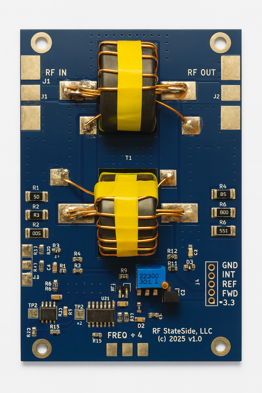
Historical fabricated RayCoupler with ferrite transformers and signal-conditioning components. This photo was AI-enhanced for lighting and clarity; the physical assembly may differ slightly. It is not a photograph of an accepted P3-prep-01 manufacturing build.
2 kW Coupler in Bud CU-234 Enclosure

Historical 2 kW RayCoupler assembly installed in a Bud Industries CU-234 aluminum enclosure. This build is designed for clean inline integration with RF IN / RF OUT mainline connectors, with the sample port brought out via a side-panel BNC connector and the frequency counter output routed to a dedicated SMA connector for direct connection to a controller, meter, or MCU frequency input.
Historical Measured Performance & Calibration
Historically fabricated RayCoupler hardware was characterized with a vector network analyzer over the HF/VHF band. The measurements below show mainline return loss (S11), insertion loss (S21), and sampler-port coupling over a 2–54 MHz sweep. These results do not establish the RF performance of the published SOD-123 revision or every new build.
S11 & S21 – 2 MHz to 54 MHz Sweep (Recalibrated)
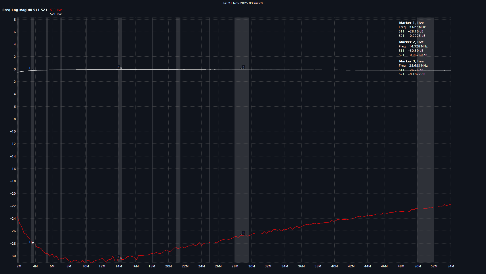
Historical mainline markers record: at 3.6 MHz S11 ≈ −27.9 dB, S21 ≈ −0.218 dB; at 14.3 MHz S11 ≈ −30.38 dB, S21 ≈ −0.053 dB; and at 28.9 MHz S11 ≈ −27.06 dB, S21 ≈ −0.094 dB. These measured points are observations of the tested hardware, not guaranteed band-wide specifications.
Sampler Port Coupling – 2 MHz to 54 MHz
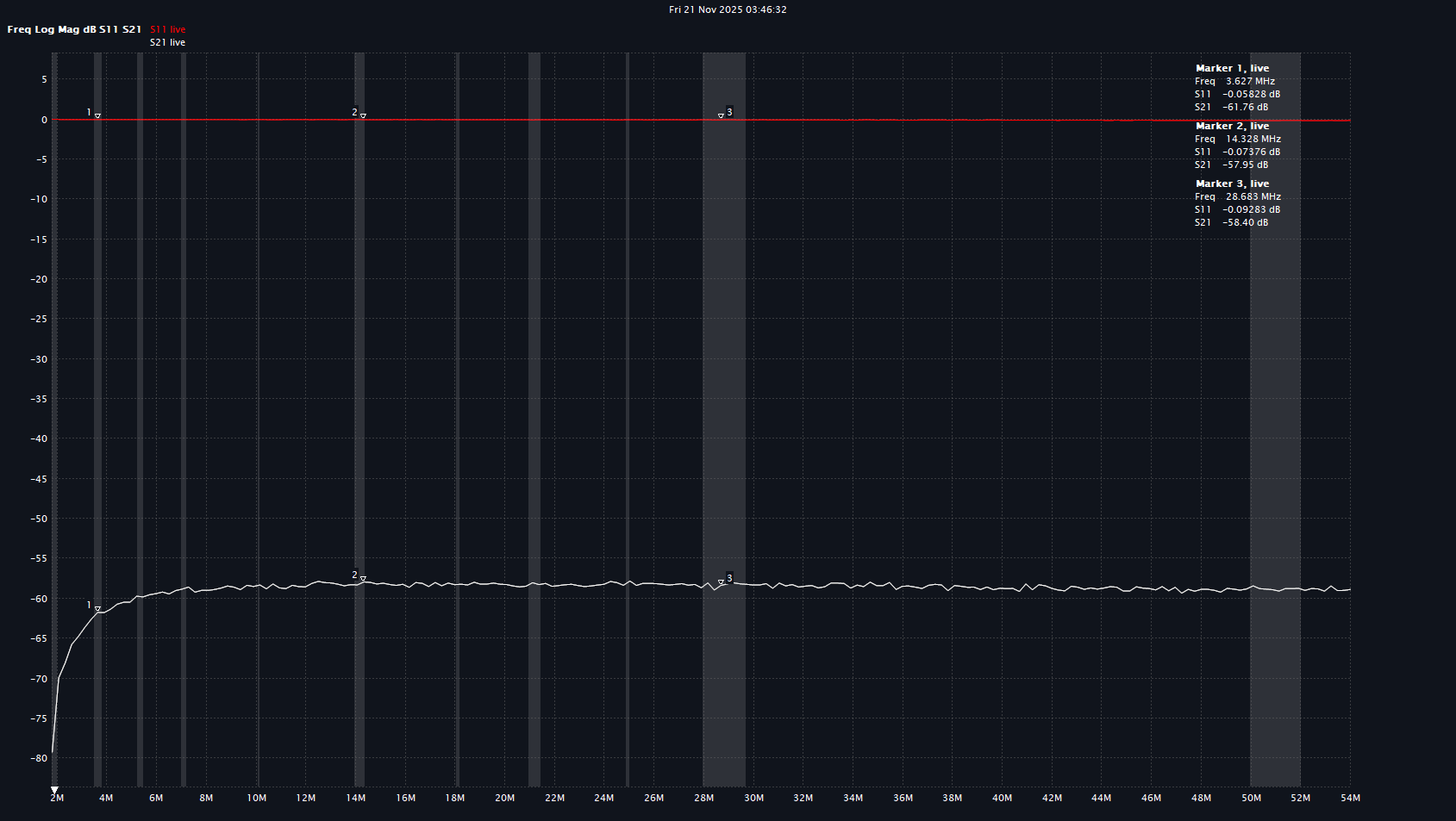
Historical sampler-port markers record: at 3.6 MHz S21 ≈ −61.76 dB; at 14.3 MHz S21 ≈ −57.95 dB; and at 28.9 MHz S21 ≈ −58.40 dB. The readings vary with frequency. Approximately −58 dB describes the historical sense-port result, not an exact coupling factor for all frequencies, assemblies or revisions.
Historical Measurement System Evidence
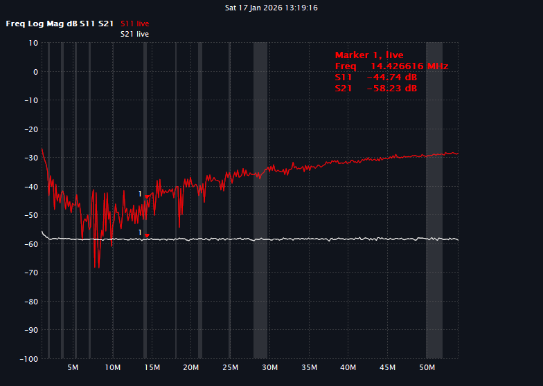
January 17, 2026 NanoVNA capture supplied by Ray: S21 −58.23 dB at 14.426616 MHz on historical tested hardware and sense-port configuration. This marker supports the approximate −58 dB description; it does not validate P3-prep-01.
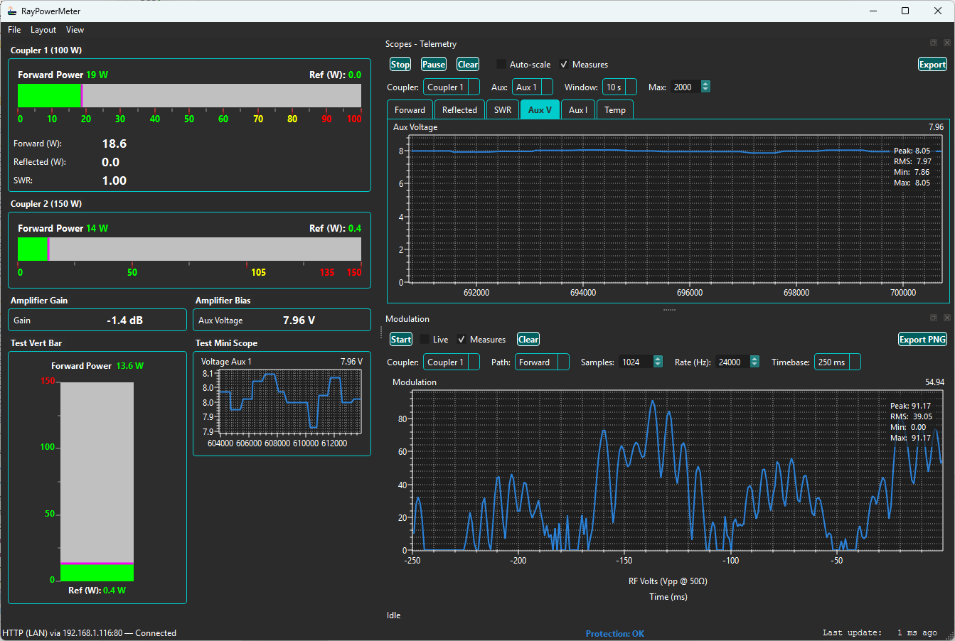
Historical RayPowerMeter system integration supplied by Ray, December 18, 2025. Dashboard channel labels and values belong to that session; they are not released configuration ratings or independent calibration evidence for the current SOD-123 manufacturing package.
The public calibration reference preserves 19 measured forward points through 250 W for the historical 200 W configuration and 14 through 1500 W for the historical 2 kW configuration. Estimated endpoints and experimental reflected adjustments are identified separately. Each new system needs its own calibration, ADC-range checks and interrupt verification.
Interested in RayCoupler?
Study the published design, build and test your own implementation, modify it, and contribute improvements. Contact Ray for engineering discussion, integration questions or collaboration.